Mastering Image Distance: The Physics Behind Capturing the Perfect Shot

Welcome to Tophinhanhdep.com, your ultimate resource for stunning visuals, high-resolution photography, and creative design inspiration. While we’re passionate about the art of image creation, we also believe that a deeper understanding of the science behind it can unlock new levels of artistic control and technical precision. Today, we delve into a fundamental concept in optics that underpins almost every photograph you’ve ever admired: how to calculate the distance of an image formed by a lens. This isn’t just theoretical physics; it’s the bedrock for achieving sharp focus, understanding depth of field, and manipulating perspective – essential skills for anyone creating beautiful photography, whether for aesthetic wallpapers, professional stock photos, or intricate digital art.
Lenses are the eyes of our cameras, the magic behind our magnifying glasses, and the precision tools in our microscopes. They bend light in predictable ways to form images, and understanding these predictions allows photographers and visual designers to consciously craft their vision. From capturing the intricate details of nature photography to conveying deep emotions through a carefully blurred background in a portrait, the principles of lens physics are constantly at play. By grasping the relationship between an object, a lens, and the image it produces, you gain the power to transcend mere point-and-shoot and truly master the visual narrative.
This comprehensive guide will walk you through the core equations and concepts, bridging the gap between abstract physics and tangible photographic outcomes. We’ll explore the Thin Lens Equation, various sign conventions, the distinction between real and virtual images, and practical methods for applying this knowledge. Our goal at Tophinhanhdep.com is to equip you with the insights needed to not only create but also optimize and refine your visual content, ensuring every image resonates with clarity, intent, and artistic excellence.
The Thin Lens Equation: Your Blueprint for Image Formation
At the heart of understanding how lenses form images lies the Thin Lens Equation. This elegant formula provides a quantitative relationship between the focal length of a lens, the distance of an object from that lens, and the distance where its image will be formed. For photographers and visual artists on Tophinhanhdep.com, this equation isn’t just numbers; it’s the key to predicting focus, manipulating background blur (bokeh), and setting up dynamic compositions.
The most common form, often referred to as the Gaussian form, is expressed as:
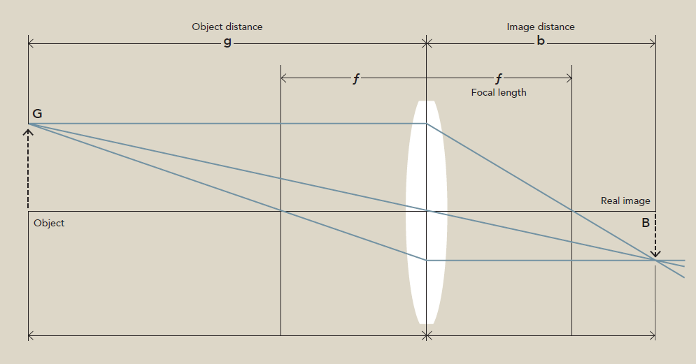
1/f = 1/o + 1/i

Where:
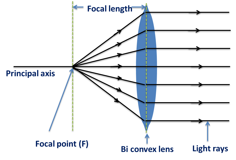
frepresents the focal length of the lens. This is an inherent property of the lens, defining its magnifying power and field of view. A positivefindicates a converging (convex) lens, which brings light rays together, while a negativefsignifies a diverging (concave) lens, which spreads light rays apart. Understanding focal length is paramount for photographers choosing between wide-angle lenses for expansive nature scenes and telephoto lenses for capturing distant wildlife or compelling portraits with compressed backgrounds.ostands for the object distance, which is the distance from the center of the lens to the object you are photographing. This is a critical variable controlled by the photographer. Adjusting the object distance directly impacts where the image will be formed and its magnification.idenotes the image distance, the distance from the center of the lens to where the image is formed. This is the value we often seek to calculate. If the image distance is positive, a “real” image is formed, which can be projected onto a screen (or a camera sensor). If it’s negative, a “virtual” image is formed, which cannot be projected but can be seen by looking through the lens, much like with a magnifying glass.
This equation is valid for “thin lenses,” meaning lenses whose thickness is negligible compared to their focal length and the object/image distances. It also applies to “paraxial rays,” which are light rays traveling close to the optic axis. While these are idealizations, the thin lens equation provides remarkably accurate predictions for most photographic scenarios and is the foundation for more complex optical designs.
Delving Deeper into Lens Characteristics and Power
Beyond just calculating i, the Thin Lens Equation also helps us understand other crucial aspects of lens performance:
-
Lens Power (P): The power of a lens is defined as the inverse of its focal length, measured in diopters (D) when the focal length is in meters (
P = 1/f). A higher diopter value means a stronger lens with a shorter focal length. This concept is particularly relevant for optometrists designing corrective lenses, but in photography, it indirectly relates to how “strong” a lens is in terms of magnification. For instance, close-up filters often add diopter power to a lens, effectively shortening its focal length to allow for closer focusing distances and greater magnification – a technique often used in macro photography to capture the intricate beauty of small subjects for Tophinhanhdep.com’s nature photography collections. -
Linear Magnification (M): The linear magnification
Mtells us how much larger or smaller the image is compared to the object, and whether it’s inverted or erect. It’s calculated asM = -i/o.- If
|M| > 1, the image is magnified. - If
|M| < 1, the image is diminished (smaller). - If
Mis negative, the image is inverted (upside down). This is typical for real images formed by converging lenses, as seen in a camera. - If
Mis positive, the image is erect (right-side up). This is characteristic of virtual images, such as those seen through a magnifying glass.
- If
Understanding magnification is invaluable for visual artists aiming for specific effects. For example, capturing a striking portrait for an aesthetic image collection on Tophinhanhdep.com might require subtle magnification and an inverted real image on the sensor, which is then corrected digitally. Conversely, a visual designer creating digital art might intentionally simulate specific magnification effects for stylistic purposes.
The Thin Lens Equation, therefore, isn’t just an abstract formula. It’s a powerful tool that quantitatively links your creative decisions (object distance, desired magnification) with the physical properties of your lens (focal length) and the resulting image formation (image distance, real/virtual, inverted/erect). Mastering this equation allows for intentional control over the visual outcomes, enhancing everything from high-resolution stock photos to deeply emotional and sad/emotional imagery where precise focus can make or break the narrative.
1.1. Sign Conventions: The Language of Lenses
Accurate use of the Thin Lens Equation hinges entirely on understanding and consistently applying sign conventions. These conventions dictate whether a distance or focal length is positive or negative, which in turn tells us about the nature of the object, image, and lens. Without them, the calculations would be ambiguous, leading to incorrect predictions about image formation. For Tophinhanhdep.com users involved in detailed photo manipulation or visual design, mastering these conventions ensures that simulated lens effects are physically accurate.
There are primarily two main sign conventions: the “common Gaussian form” used in many introductory texts and the “Cartesian sign convention” favored in more advanced optics.
1.1.1. Common Gaussian Form Sign Convention
This convention is often implicitly used with the 1/f = 1/o + 1/i equation. Its rules are generally simpler but require careful interpretation of the results:
- Focal Length (f):
- Positive (+) for converging lenses (convex lenses). These lenses bring parallel light rays to a focus. Most camera lenses are converging lenses.
- Negative (-) for diverging lenses (concave lenses). These lenses spread parallel light rays apart, making them appear to originate from a focal point behind the lens.
- Object Distance (o):
- Always considered positive (+) for real objects. A real object is one from which light rays actually originate or pass through. This is almost always the case in standard photography.
- Image Distance (i):
- Positive (+) for real images. A real image is formed when refracted light rays actually converge at a point. Real images can be projected onto a screen (like a camera sensor) and are always on the opposite side of the lens from the object.
- Negative (-) for virtual images. A virtual image is formed when refracted light rays appear to diverge from a point. Virtual images cannot be projected onto a screen and are always on the same side of the lens as the object. This is what you see when looking through a magnifying glass.
- Linear Magnification (M):
- Negative (-) for inverted images.
- Positive (+) for erect images.
This convention is straightforward for single-lens systems and is perfectly adequate for most photographic calculations. For example, if you calculate a negative image distance, you immediately know the image is virtual and located on the same side of the lens as your object. This helps you understand why some lens configurations (like a very close object to a convex lens) act like a magnifying glass, producing a virtual, erect, and magnified image.
1.1.2. Cartesian Sign Convention
While the common Gaussian form is intuitive, the Cartesian sign convention offers a more consistent and powerful approach, especially for complex optical systems involving multiple lenses or mirrors. Its strength lies in its consistency with coordinate geometry.
The core principles are:
- Light Travels from Left to Right: All diagrams are drawn with incident light originating from the left and traveling towards the right.
- Origin at the Lens Center: All distances are measured from the optical center of the lens (or the vertex of a mirror).
- Positive and Negative Directions:
- Distances measured against the direction of light travel (to the left of the lens) are negative (-).
- Distances measured in the direction of light travel (to the right of the lens) are positive (+).
- Heights above the principal axis are positive (+); heights below are negative (-).
- Specific Applications:
- Object Distance (o): For a real object (light originates from it), it is always placed to the left of the lens, so
ois always negative (-). This is a crucial distinction from the common Gaussian convention. - Image Distance (i):
- If the image forms to the right of the lens (real image),
iis positive (+). - If the image forms to the left of the lens (virtual image),
iis negative (-).
- If the image forms to the right of the lens (real image),
- Focal Length (f):
- For a converging lens, its principal focal point is where parallel rays converge to the right of the lens, so
fis positive (+). - For a diverging lens, parallel rays appear to diverge from a focal point to the left of the lens, so
fis negative (-).
- For a converging lens, its principal focal point is where parallel rays converge to the right of the lens, so
- Object Distance (o): For a real object (light originates from it), it is always placed to the left of the lens, so
Using the Cartesian convention, the Thin Lens Equation is often written as 1/f = 1/o' + 1/i, where o' is now the magnitude of the object distance, and o itself is treated as negative. Or, more simply, it maintains the same 1/f = 1/o + 1/i form but requires you to input the object distance o as a negative value for a real object. This might seem counterintuitive at first, but its systematic nature makes it easier to track signs through cascading lens systems, which are common in advanced camera optics or scientific instruments.
For digital photography and image editing on Tophinhanhdep.com, understanding these conventions aids in:
- Photo Manipulation: When digitally creating or altering optical effects, having a consistent sign convention helps simulate real-world lens behavior accurately, from subtle changes in depth of field to dramatic perspective shifts.
- Visual Design: Graphic designers crafting digital art or creative ideas involving optical illusions can leverage these principles to ensure their visual representations are convincing and consistent.
1.1.3. Newtonian Form: An Alternative Perspective
While the Gaussian and Cartesian forms relate distances from the lens, the Newtonian form of the thin lens equation takes a different approach. It focuses on the “extrafocal distances” – the distances of the object and image from their respective focal points, rather than from the lens itself.
The Newtonian form is expressed as:
xo * xi = f^2
Where:
xois the distance from the object to the first focal point.xiis the distance from the image to the second focal point.fis the focal length.
This form provides an equivalent treatment but is less commonly used in introductory physics or practical photography contexts where the Gaussian form typically suffices due to its direct relation to the lens’s optical center. However, for those interested in the historical development of optics or exploring alternative mathematical representations, it highlights the rich interconnectedness of lens properties. On Tophinhanhdep.com, while less directly applicable to daily photography, it’s an example of the depth of optical theory that underpins even the simplest beautiful photography.
Real vs. Virtual Images: Capturing and Perceiving Light
The nature of the image formed by a lens — whether it’s real or virtual — is a critical concept in photography and visual design. This distinction not only influences how an image is captured but also how it is perceived. The Thin Lens Equation, through the sign of the calculated image distance, directly tells us which type of image will be formed. Understanding this is fundamental for photographers to predict how their subjects will appear and for visual artists to simulate accurate optical effects.
2.1. Real Image Formation
A real image is formed when light rays that pass through a lens actually converge at a specific point in space. This means the light energy is physically present at that location, and if you place a screen there, the image will be projected onto it.
Key characteristics of real images:
- Projectable: They can be captured on a light-sensitive surface, like the film or digital sensor in a camera, or projected onto a viewing screen. This is the mechanism by which all cameras operate.
- Inverted: Real images formed by a single converging lens are always inverted (upside down) and often laterally reversed (left-right flipped). Camera sensors capture this inverted image, and the camera’s internal processing or photographic software then flips it to present it correctly to the viewer.
- Located on the Opposite Side: For a single converging lens, a real image forms on the side of the lens opposite to the object.
- Formed by Converging Lenses: Real images are typically formed by converging (convex) lenses when the object is placed farther away from the lens than its focal length (
o > f).
In the context of Tophinhanhdep.com and photography:
Every high-resolution photograph, every stunning wallpaper, and every meticulously composed stock photo owes its existence to the formation of a real image on a camera sensor. When you focus your camera, you are essentially adjusting the object distance (o) and the lens elements to ensure that the real image of your subject is formed precisely on the sensor plane.
- Depth of Field: The concept of depth of field, crucial for aesthetic, nature, and portrait photography, directly relates to real image formation. A shallow depth of field, where the background is beautifully blurred (bokeh), is achieved by precisely focusing on the subject, causing light rays from foreground and background elements to form their real images slightly in front of or behind the sensor, making them appear out of focus.
- Digital Photography & Editing Styles: Understanding real images helps in post-processing. Knowing how a real image is formed allows for more effective digital editing styles, such as correcting optical aberrations (like chromatic aberration or distortion inherent in lenses) that affect the quality of the real image captured. AI Upscalers, for instance, might be trained on the characteristics of real images to enhance detail and sharpness, even when the original real image might have been slightly soft.
- Creative Ideas & Mood Boards: The ability to form real images opens up a vast array of creative possibilities. From sharp, detailed macro shots of flowers for nature photography to dramatic, emotionally charged portraits with selective focus for sad/emotional or beautiful photography, the real image is the tangible output of your artistic vision.
2.2. Virtual Image Formation
A virtual image is quite different. It is formed when light rays, after passing through a lens, appear to diverge from a point, but do not actually converge there. You cannot project a virtual image onto a screen.
Key characteristics of virtual images:
- Not Projectable: You cannot capture a virtual image on a sensor or screen.
- Erect: Virtual images are typically erect (right-side up) relative to the object.
- Located on the Same Side: For a single lens, a virtual image forms on the same side of the lens as the object.
- Seen Through the Lens: You perceive a virtual image by looking through the lens.
- Formed by Converging Lenses (Specific Case): A converging lens produces a virtual image when the object is placed between the focal point and the lens (
o < f). This is how a magnifying glass works. - Formed by Diverging Lenses (Always): A diverging lens always forms a virtual, erect, and diminished image, regardless of the object’s position.
In the context of Tophinhanhdep.com and visual perception: While virtual images aren’t directly captured by cameras in the same way real images are, they are crucial for understanding optical instruments and visual perception:
- Magnifying Glasses: The common magnifying glass is an excellent example of virtual image formation. When you hold an object close to a convex lens, you see a magnified, erect virtual image. This principle might inspire visual designers to create abstract art or photo manipulations that mimic the exaggerated perspectives seen through such lenses.
- Viewfinders: In older cameras or certain optical instruments, virtual images are sometimes used in viewfinders to allow the photographer to compose the shot.
- Digital Art & Simulation: Visual designers and graphic artists on Tophinhanhdep.com can simulate virtual image effects for artistic purposes. Imagine digital art that creates the impression of looking through a vintage magnifying glass, distorting and enlarging elements to evoke a specific mood or creative idea.
- Understanding Lens Types: The knowledge that diverging lenses always produce virtual images helps in understanding specific lens applications, like those used in corrective eyewear for nearsightedness, or certain elements within complex camera lens designs that help manage aberrations.
The Thin Lens Equation seamlessly integrates both real and virtual image formation. If your calculation for i (image distance) is positive, you have a real image. If i is negative, you have a virtual image. This simple sign change holds profound implications for how images are captured, processed, and creatively utilized across the diverse categories of Tophinhanhdep.com, from abstract backgrounds to thematic photo collections.
Practical Application: From Theory to Photographic Mastery
The theoretical understanding of the Thin Lens Equation and image types gains immense power when translated into practical application. For the discerning photographer, visual designer, and image enthusiast on Tophinhanhdep.com, these practical insights mean the difference between guessing and truly knowing how your lens will behave. From experimentally determining a lens’s focal length to developing a deeper intuition for object and image distances, these applications bridge physics and art.
3.1. Determining Focal Length: The Heart of the Lens
The focal length (f) is arguably the most defining characteristic of a lens, influencing everything from the field of view to the compression of perspective. Knowing the precise focal length of your lens, even if it’s not explicitly marked, is vital for predicting image behavior.
3.1.1. Experimental Determination Methods
Several practical methods exist to determine a lens’s focal length:
-
Distant Light Source Method: This is one of the simplest and most common ways, especially for converging lenses.
- Principle: Light rays from a very distant object (like the sun or a faraway building) can be considered essentially parallel by the time they reach your lens. Converging lenses bring parallel light rays to focus at their principal focal point.
- Procedure: Hold the converging lens and project the image of a distant object onto a piece of paper or a screen. Adjust the distance of the paper from the lens until the image is as sharp and small as possible. The distance from the lens to the paper at this point is the approximate focal length.
- Safety Note: NEVER look directly at the sun through a lens, as this can cause severe eye damage. Always use a projection method.
- Tophinhanhdep.com Relevance: This method allows photographers to quickly verify or estimate the focal length of a new or unmarked lens, which is crucial for planning shots, especially in high-resolution digital photography where precise focal length influences everything from composition to specific editing styles. For macro photographers, understanding how “effective focal length” changes with extension tubes is an advanced application of this concept.
-
Using Ray Diagrams: While not an experimental method in the traditional sense, drawing accurate ray diagrams can qualitatively and even semi-quantitatively help understand focal length’s role.
- Principle: Ray diagrams use a few key light rays with predictable paths through a lens to graphically locate the image. By working backward from a known object and image position, one can infer the focal length.
- Tophinhanhdep.com Relevance: Visual designers and graphic artists use simplified ray tracing principles in their software to simulate realistic light behavior and lens effects. Understanding the fundamentals of ray diagrams can inspire creative ideas for abstract images or photo manipulations where light interaction is central to the design.
-
Light Box / Optical Bench Method: More precise experimental setups involve an optical bench with a light source, an object, and a screen.
- Principle: By systematically varying the object distance (
o) and measuring the corresponding image distance (i), you can plug these values into the Thin Lens Equation (1/f = 1/o + 1/i) to calculatef. Collecting multiple data points and averaging the calculated focal length provides greater accuracy. - Tophinhanhdep.com Relevance: This controlled environment allows for a deeper understanding of how different focal lengths affect image characteristics, informing the choice of lenses for specific photographic styles (e.g., the wide angle for expansive nature shots vs. the telephoto for compressing backgrounds in portraits). This precision is invaluable for achieving the sharpness demanded by stock photos and optimizing images.
- Principle: By systematically varying the object distance (
Understanding the focal length of a lens is foundational for all photographers. It directly impacts how you frame a shot, whether you achieve shallow depth of field for an aesthetic portrait, or capture a vast landscape for a beautiful nature background. For those delving into image tools like AI Upscalers, knowing the lens characteristics can even inform how the AI interprets and enhances image details, especially in cases of lens-induced distortions.
3.2. Modeling the Thin Lens Equation: A Hands-On Approach
Beyond simply plugging numbers into a formula, actively modeling the Thin Lens Equation through experimentation offers a profound and intuitive understanding of its principles. This hands-on process allows you to observe the relationship between object and image distances firsthand and derive the equation from your own data, reinforcing the underlying physics in a way that resonates with practical photographers and visual artists.
3.2.1. Data Collection: Observing Image Formation
The core of this modeling process involves systematically varying the object distance (do or o) from a converging lens and meticulously measuring the corresponding image distance (di or i) where a focused, real image is formed on a screen.
- Setup: An introductory optical system (optical bench) with an LED object, a converging lens, and a viewing screen is ideal.
- Initial Focal Length Estimation: Before detailed data collection, estimate the lens’s focal length using the distant light source method. This ensures that you only collect data for scenarios that produce real images (object distance
omust be greater than the focal lengthf). - Systematic Variation: Place the LED object at various distances from the lens (e.g., starting close to
fand moving progressively farther away). For each object distance, adjust the screen until a sharp, focused image is achieved, and record the image distance. - Data Range: It’s crucial to collect a wide range of values, from object distances slightly greater than
fto very large object distances. This broad range will reveal the full, non-linear nature of the relationship. - Tophinhanhdep.com Relevance: This process simulates the actions of a photographer adjusting focus. Understanding how changing object distance affects image distance (and thus focus) is essential for mastering digital photography, achieving sharp high-resolution images, and controlling depth of field for specific aesthetic or emotional effects in your photography.
3.2.2. Data Analysis: Uncovering the Relationship
Once data on object distance and image distance is collected, the next step is to analyze it graphically to reveal the underlying mathematical relationship.
-
Initial Graph: Plot image distance (
di) on the y-axis against object distance (do) on the x-axis.- Observation: Students will typically observe a hyperbolic curve. It might initially look linear with a negative slope if the data range isn’t wide enough, but extending the range will reveal its true non-linear, asymptotic nature. This visual representation alone provides insight: as the object moves further away, the image distance approaches the focal length, and as the object moves closer to the focal point, the image distance rapidly moves further away.
- Tophinhanhdep.com Relevance: This hyperbolic relationship is directly observable in photography. Think about how much more dramatically your focus changes when an object is very close versus when it’s far away. This dictates lens design, autofocus systems, and the techniques photographers use for portrait vs. landscape photography.
-
Linearization: To derive an algebraic equation, the non-linear graph needs to be “linearized” or “re-expressed.” This involves transforming the variables so that plotting them results in a straight line.
- Process: After experimenting with inverse relationships, students will discover that plotting the inverse of the image distance (1/di) on the y-axis against the inverse of the object distance (1/do) on the x-axis yields a linear graph.
- Tophinhanhdep.com Relevance: Understanding linearization helps in advanced image analysis or even in developing new image tools. For instance, some calibration processes for camera lenses might use similar mathematical transformations to correct distortions or optimize performance, which is vital for maintaining the integrity of high-resolution stock photos.
-
Equation Derivation: From the linearized graph, you can derive the equation in the standard linear form
y = mx + b.- Mapping to Variables:
1/di = (m)(1/do) + b - Interpreting Slope (m): The slope of this linearized graph will consistently be found to be approximately -1. This indicates an inverse relationship between the inverse of image distance and the inverse of object distance. In the context of the Thin Lens Equation, this
m = -1term implies1/di = -1/do + b. - Interpreting Y-intercept (b): The y-intercept (
b) will have units of inverse length (e.g., 1/cm). Crucially, students will discover that this y-intercept value is very close to the inverse of the lens’s experimentally determined focal length (1/f). This is a powerful moment, as it reveals thatb = 1/f.
- Mapping to Variables:
Therefore, substituting these findings back into the linearized equation:
1/di = -1/do + 1/f
Rearranging this gives us the familiar Thin Lens Equation:
1/f = 1/do + 1/di
This empirical derivation from collected data provides a robust understanding of why the equation is structured the way it is.
3.2.3. Conclusion Discussion: Unifying Theory and Practice
A whole-class discussion, comparing the graphs and equations from different lab groups (especially those using lenses with different focal lengths), solidifies this understanding.
- Slope Consensus: The consistent slope of -1 reinforces the fundamental relationship.
- Y-intercept as Focal Length: The varying y-intercepts, directly corresponding to the inverse of each lens’s focal length, provides compelling evidence for
1/fbeing the constant that defines the lens’s optical power. This highlights how focal length remains constant for a given lens throughout any experiment. - Generalizability: The remarkable discovery is that this equation, derived from a converging lens forming real images, also works (with appropriate sign conventions) for diverging lenses and even mirrors, making it a universal principle in introductory optics.
Tophinhanhdep.com Impact: This hands-on modeling is directly relevant to mastering visual creation:
- Photographic Intuition: It builds a deep intuition for how lenses work, allowing photographers to anticipate effects like background blur or perspective compression without constant trial and error. This is invaluable for creative ideas and crafting specific emotional imagery.
- Optimal Settings: Understanding this relationship helps in selecting optimal lens and aperture settings for different scenarios, ensuring beautiful photography and high-resolution output.
- Visual Storytelling: By understanding the physics, you gain more control over your visual storytelling. Whether you’re curating thematic collections, designing a mood board, or working on sophisticated photo manipulation, this fundamental knowledge enhances your ability to achieve precise and impactful results.
- Beyond the Camera: For visual designers and digital artists, these principles allow for the creation of more convincing and realistic digital art and visual effects, mimicking the very laws of light that govern the physical world.
By embracing the science behind the lenses, Tophinhanhdep.com users can elevate their craft, transforming technical understanding into limitless creative potential, ultimately producing images that are not just seen, but felt and experienced. We invite you to explore our vast collections of wallpapers, backgrounds, and aesthetic images, all created with an underlying mastery of the very principles we’ve discussed today.